Wednesday, March 22, 2017

Week 7 (March 15 - March 22)

After calling a couple places to order metal for the links we found a local place. We learned about it when calling Coast Aluminium and they recommended Gorilla Metals. Gorilla Metals carries flat stock aluminium in the size we wanted to get, so we used it to make the links. We did not get the metal for the tilt cradle. This week we will get the metal for the tilt cradle and start working on that.

The tilt links are made out of aluminium 6061. They are a 1/4 inch thick by 1 inch wide. These are test pieces used to verify operation and motion path. If binding becomes an issue then they can be replaced by links designed to be used with flanged ball bearings for smoother operation.  

We completed the bars for the scissor lift. We cut the square tubing to size. These wont take much time to make as they just need to be cut and drilled. 

The links were supposed to made with waterjet cutting. However, in the interest of time and money we decided to make them by cutting and drilling flat stock instead. 

Wednesday, March 15, 2017

Week 6 (3/8-3/15) Current Build Progress

We have made the follower beam last week. (see figure 1) We used 1x1 inch square tubing to make it. The gauge of the tubing was thin. When we tried to weld it there would be areas that either melted or flash rusted. A couple factors can be traced to the argon gas feed for the MIG welder. The regulator for gas feed could have been broken. Since the material is inexpensive it would be better to remake it. It needs to have solid welds since it will be holding the entire assembly. We can use a thicker gauge of 1x1 square tubing so that it will be stronger and easy to weld. In addition, we can use a different MIG welder to prevent flash rusting while welding.

Figure 1 : Follower Beam

This week we will check with Campbell Metal Supply to see if they have the flat stock that we want to use in our build. Once we get that we can finish the links for the tilt mechanism and the mechanical suspension. Already have the square tubing for the lift mechanism. We need to weld together the tilt mechanism cradle piece as well. 

Wednesday, March 1, 2017

Week 5 (March 1 - March 8)

The first presentation of the spring semester for the Active Suspension team


Week 4 (Feb 22 - Mar 1)

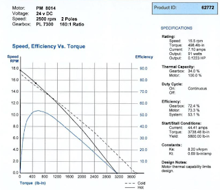
This past week we have been checking our calculations in order to submit the AS application. Another update is that after reviewing the motors that will be used in propulsion is that we have come to the conclusion that their motor will be able to power our tilt mechanism. This does not mean that the motor will be used for both applications. We made this decision since the motor that propulsion will use is cheaper than the motor that we were quoted for by Groschopp. The differences are that their motor is cheaper, less torque at similar rpm, and less amperage draw. All these are advantages rather than disadvantages. The cheaper price will help us make our budget smaller and cost effective. The motor produces 150 in lbs less torque at a similar rpm. This is fine because we don't need to move our tilt assembly at 15.5 rpm. We can move it at a lower rpm, which according to the motor spec sheet, the motor will be able to meet our torque requirements at the lower rpm. The lower amperage draw is less load on the power supply.


PM -8014 : Motor Spec Sheet