The first presentation of the spring semester for the Active Suspension team
Wednesday, March 1, 2017

Week 4 (Feb 22 - Mar 1)
This past week we have been checking our calculations in order to submit the AS application. Another update is that after reviewing the motors that will be used in propulsion is that we have come to the conclusion that their motor will be able to power our tilt mechanism. This does not mean that the motor will be used for both applications. We made this decision since the motor that propulsion will use is cheaper than the motor that we were quoted for by Groschopp. The differences are that their motor is cheaper, less torque at similar rpm, and less amperage draw. All these are advantages rather than disadvantages. The cheaper price will help us make our budget smaller and cost effective. The motor produces 150 in lbs less torque at a similar rpm. This is fine because we don't need to move our tilt assembly at 15.5 rpm. We can move it at a lower rpm, which according to the motor spec sheet, the motor will be able to meet our torque requirements at the lower rpm. The lower amperage draw is less load on the power supply.
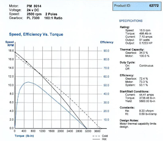

PM -8014 : Motor Spec Sheet
Wednesday, February 22, 2017
Week 3 (Feb 15 - Feb 22)
Spent this week double checking our BOM calculations. Then after we were absolutely sure that we knew how much material was needed for our project we went to get quotes. Campbell Metal Supplies has a large selection of Aluminum. The quote we got for the needed quantity of Aluminium 6061 was high. It was $404.61. This high price is most likely due to the weight and dimensions of the piece we need. We found a substitute over at Sims metal management. They do not have 6061 Aluminium on hand but they do have steel metal plate. By choosing the steel over the aluminum we would save $181.89. This is a better choice as the money can be used for extra materials or motors and since this is a prototype it's better to budget on certain aspects. The design has a large safety factor to account for the extra weight of the steel.
Wednesday, February 15, 2017
Week 2 (Feb 9 - Feb 15)
Our team is delayed on our Gantt chart. However, this is a good opportunity to revise our BOM so we can get it approved. One of the items that we will need is a DC motor that can produce enough torque to move our Tilt mechanism. Oriental Motor has motors that can supply the torque, however they are limited in their offerings from what we have seen. Groschopp is another company that manufacturers motors and they are able to supply us with a motor with a high range of customizability and torque.
We have calculated that the needed continuous torque needed to move the tilt mechanism was 644 in lbs. They are able to supply a motor that can operate at 650 in lbs at 15.8 RPM. This would be more than acceptable considering that the tilt mechanism would slowly tilt to keep the cabin stable.

We have calculated that the needed continuous torque needed to move the tilt mechanism was 644 in lbs. They are able to supply a motor that can operate at 650 in lbs at 15.8 RPM. This would be more than acceptable considering that the tilt mechanism would slowly tilt to keep the cabin stable.

Figure 1: Motor Specifications for Tilt Mechanism
As we look at the graph we can also see that operating the motor at this speed and torque would give us a high motor efficiency. It would be close to 75-77 percent.
Wednesday, February 8, 2017
Week 1 (Feb 1 - Feb8)
We are currently waiting to get out bill of materials approved in order to start building our design.
Thursday, December 1, 2016
Week 15 (Nov 30 - Dec 7)
For slide 5, here is representation of it moving - https://gfycat.com/UntidyCandidBats
For slide 6, here is representation of it moving - https://gfycat.com/EquatorialGraveAustraliansilkyterrier#?speed=0.5
Wednesday, November 30, 2016
Week 14 (Nov 24 - Nov 30)
We have begun simulating the mechanism with the cabin model made by a previous team at Spartan Superway. Minor changes were made to the Cabin Model. It needed to be scaled down to half-scale. After that it was possible to reuse the mounting plate to attach it to the suspension assembly. We would have liked to connect it to the Bogie system as well but there were issues with that in SolidWorks. However, we will keep trying to integrate everything into the simulation.
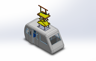

Figure 1 : Pod Car with Active Suspension
Subscribe to:
Posts (Atom)